Servo Motor Calibrator
From breadboard to custom PCB, a tuning tool built for intro electronics students.
Why I Built This
Students needed a way to tune their servos without guessing.
As a TA for intro to electronics at Wesleyan, I kept seeing students struggle to get their servo motors to a stable position. There was no good tool for it. I designed the Servo Motor Calibrator from scratch, starting on a breadboard, iterating to a protoboard, and eventually designing a custom PCB. It lets students plug in their servo, turn a dial, and stabilize the motor in seconds so they can get back to building their actual project. And if they need to recalibrate, it's just as quick the second time.
How It Works
01
Plug In
Student connects their servo motor directly to the board via a standard three-pin connector.
02
Tune
A dial lets the student adjust until the servo stabilizes at the desired position.
03
Build
With the servo dialed in and stable, students can use it directly in their own projects without further adjustment.
Three Stages
Breadboard. Protoboard. PCB.
Most projects start messy. This one went through three distinct stages before it became a tool worth putting in a student's hands.
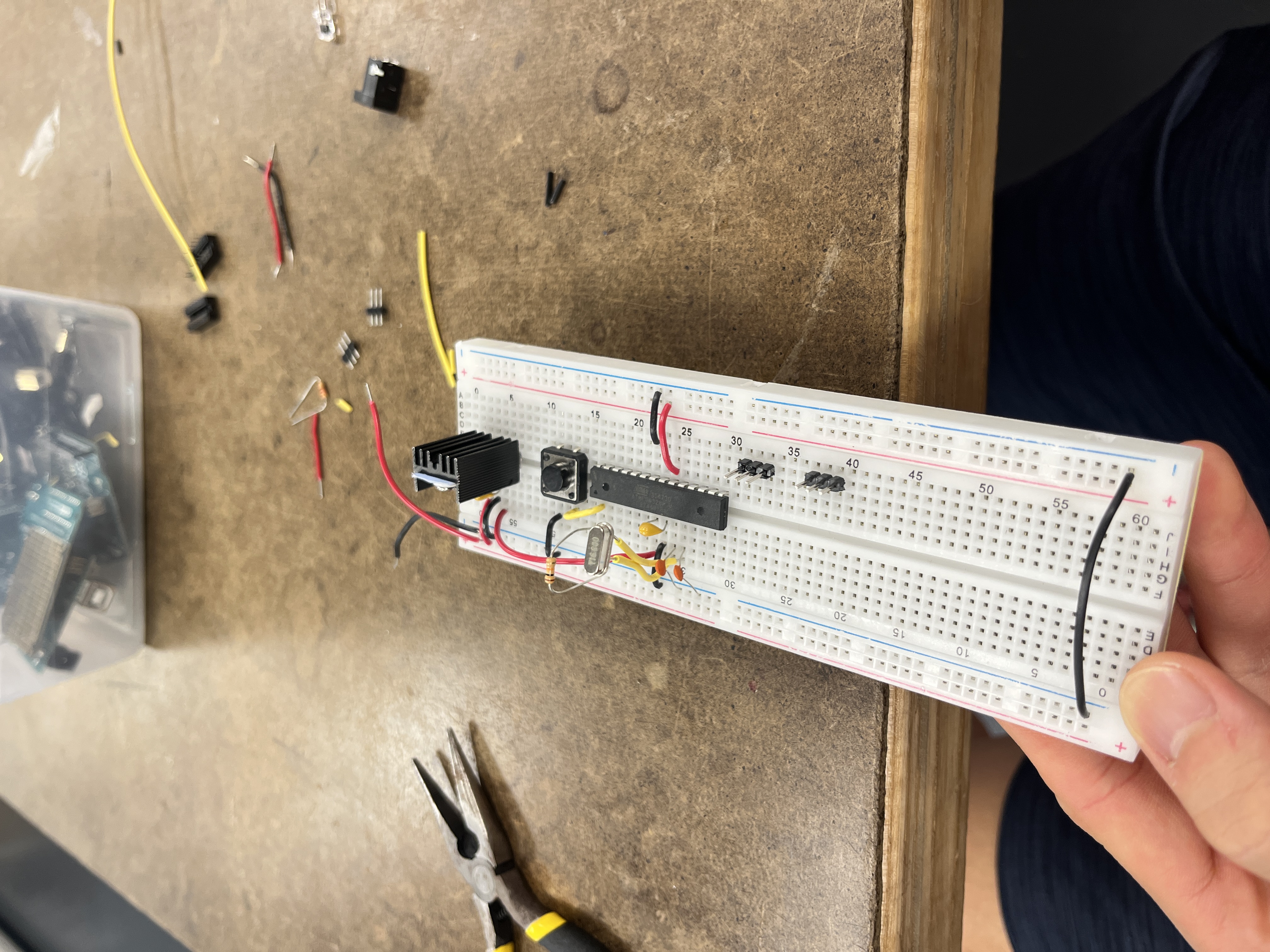
Stage 1, Breadboard prototype
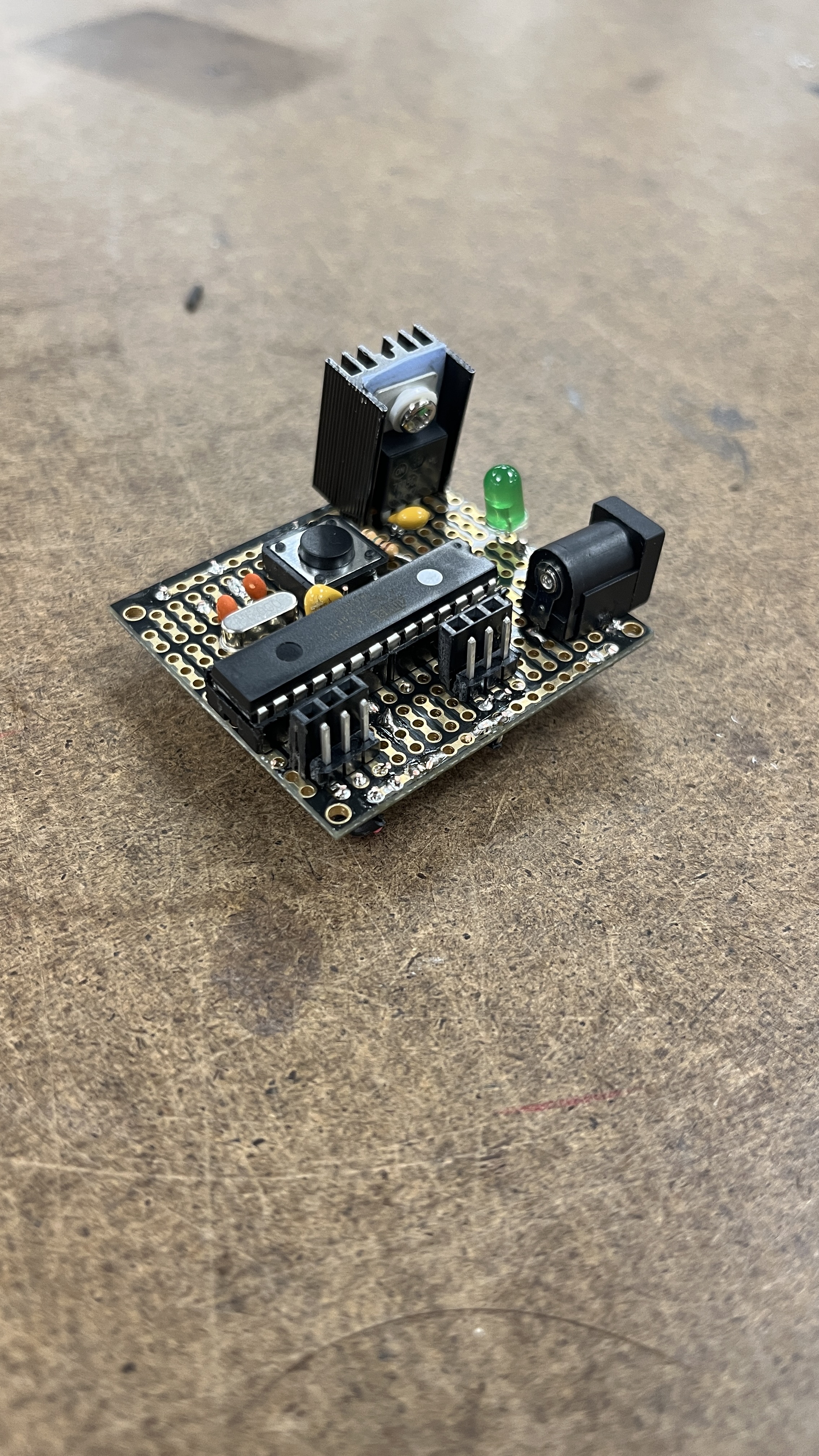
Stage 2, Protoboard
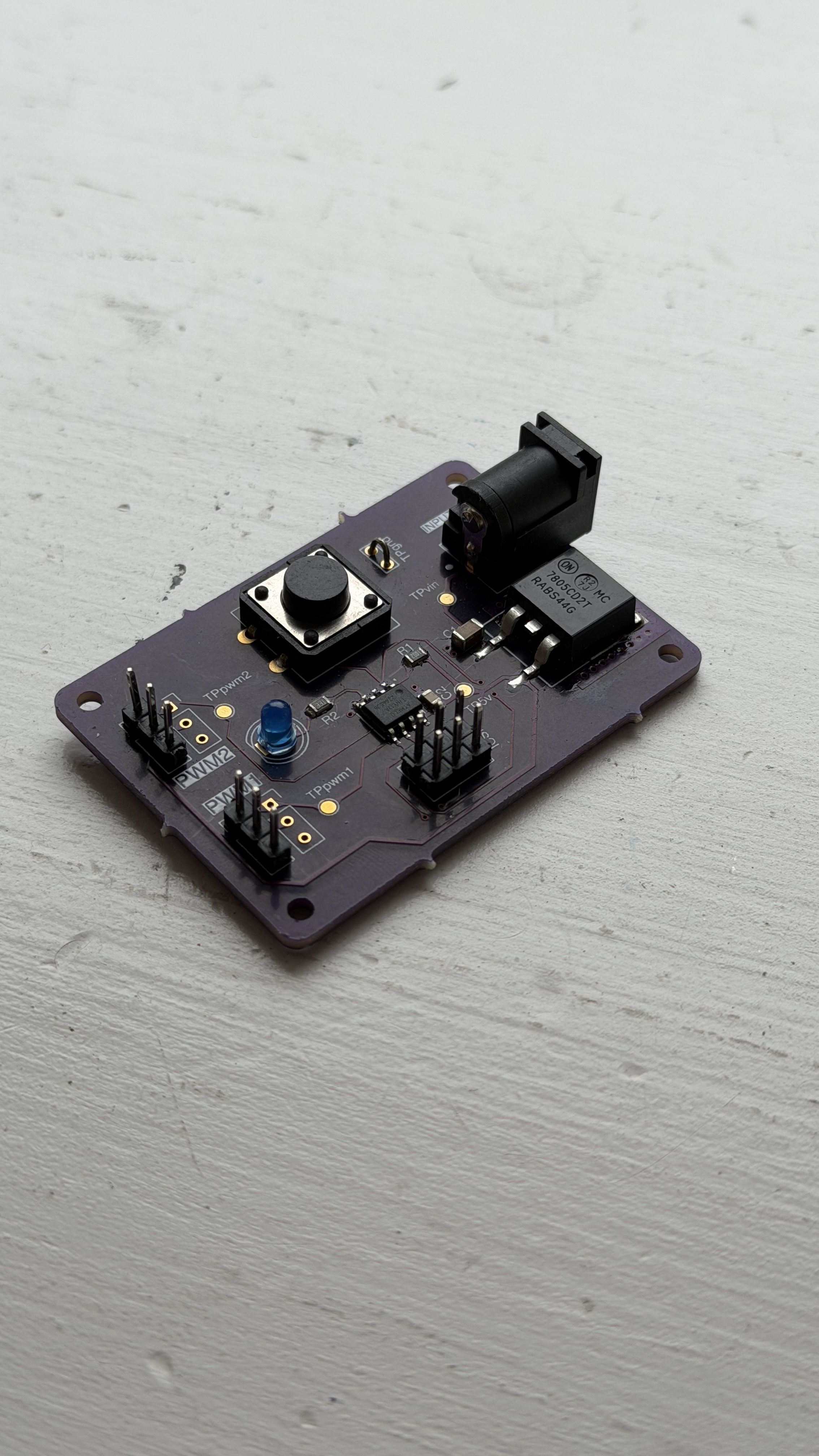
Stage 3, Custom PCB
The Design
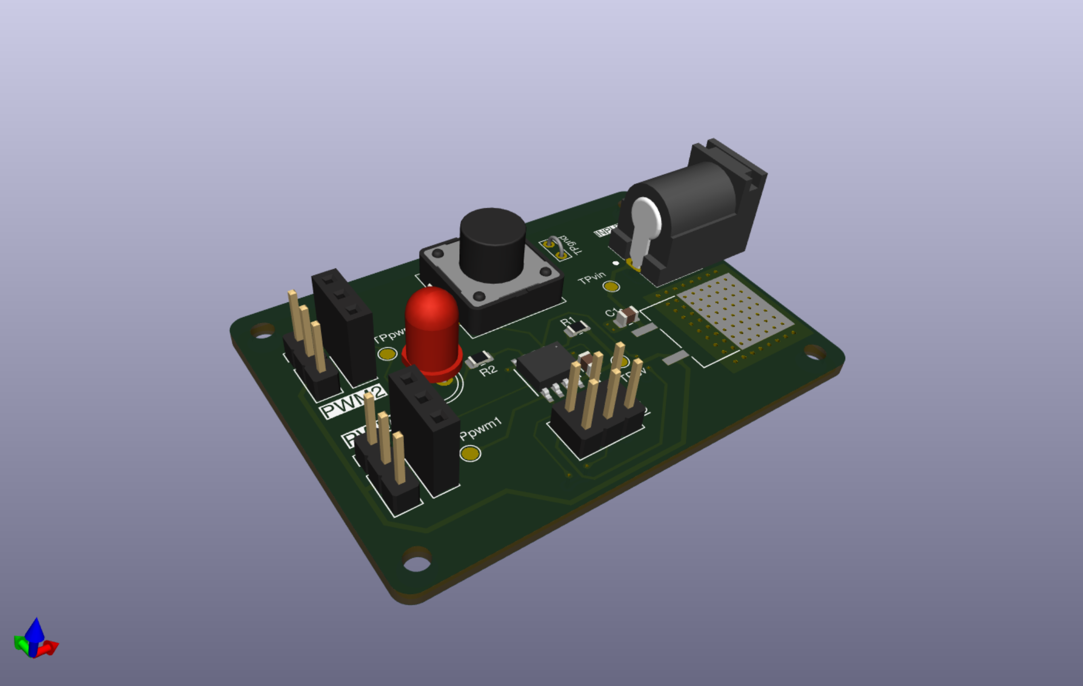
3D render, KiCad
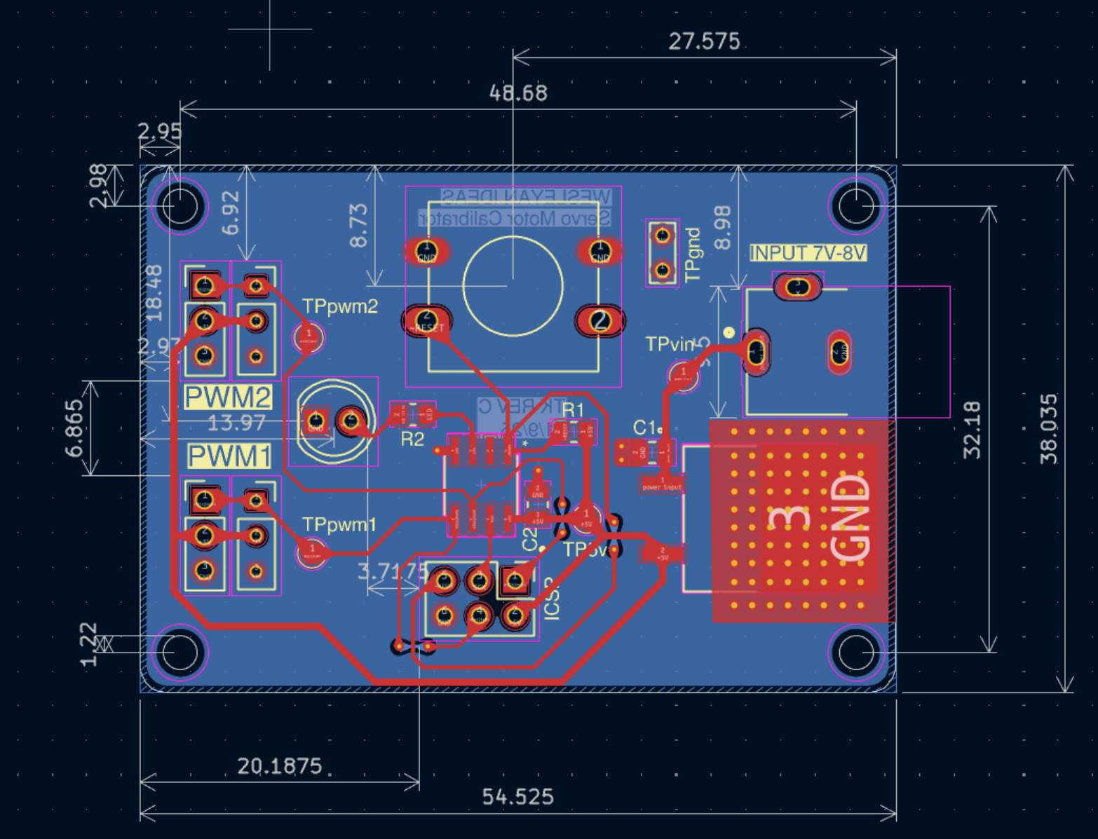
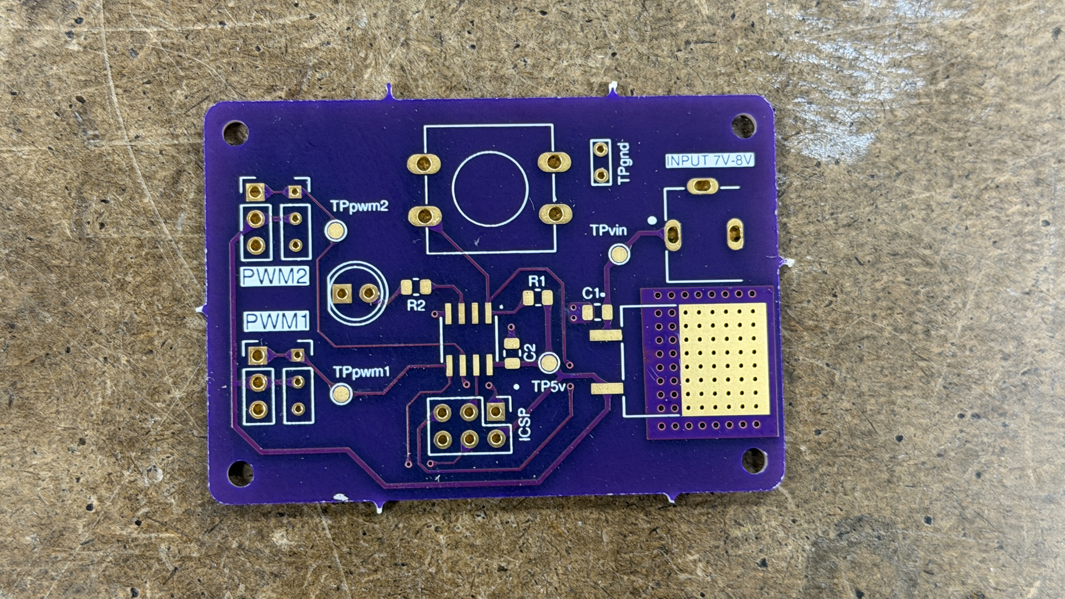
PCB layout, KiCad
Schematic
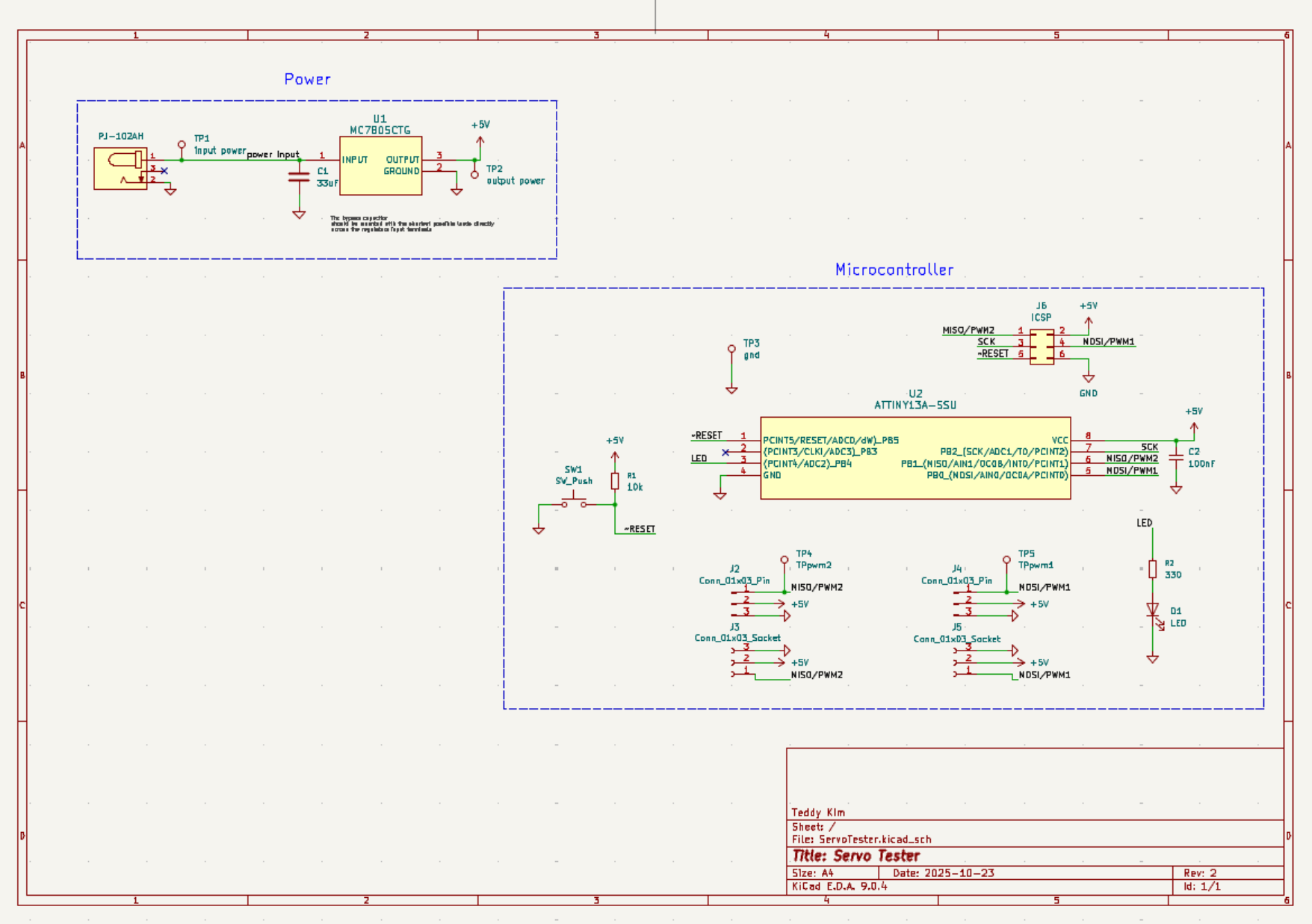
Full schematic, KiCad
Under the Hood
PCB
Custom designed in KiCad, compact form factor sized for bench use in a classroom setting.
Signal Control
PWM signal generation for standard hobby servo control.
Connector
Standard three-pin servo header compatible with all common hobby servos.
Power
DC barrel jack powered.
Iterations
Three hardware revisions from breadboard through to final PCB.
Context
Designed and built while TAing the same course the tool was used in.
Built With
Design
Hardware
This went from a breadboard to a custom PCB I designed and put in students' hands. If you're looking for someone who can take hardware from concept to production, I'd love to talk.
Get in Touch