
Servo Motor Calibrator
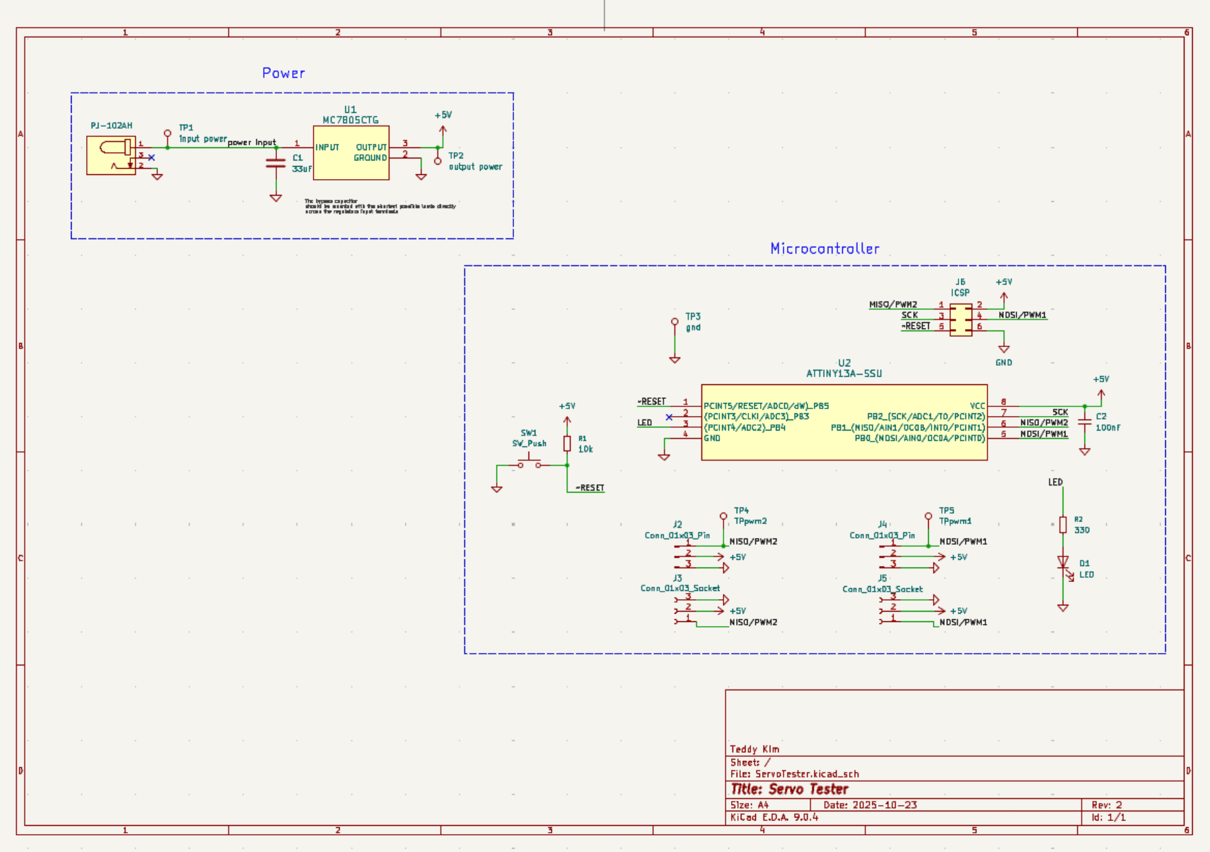
Schematic Capture
Initally, I browsed through different micrcontrollers and linear regulators before settling on the right one. I tried to pick a linear regulator that wasn't too powerful to save on cost.
Also, I chose a microcontroller that had only the functionally I needed.
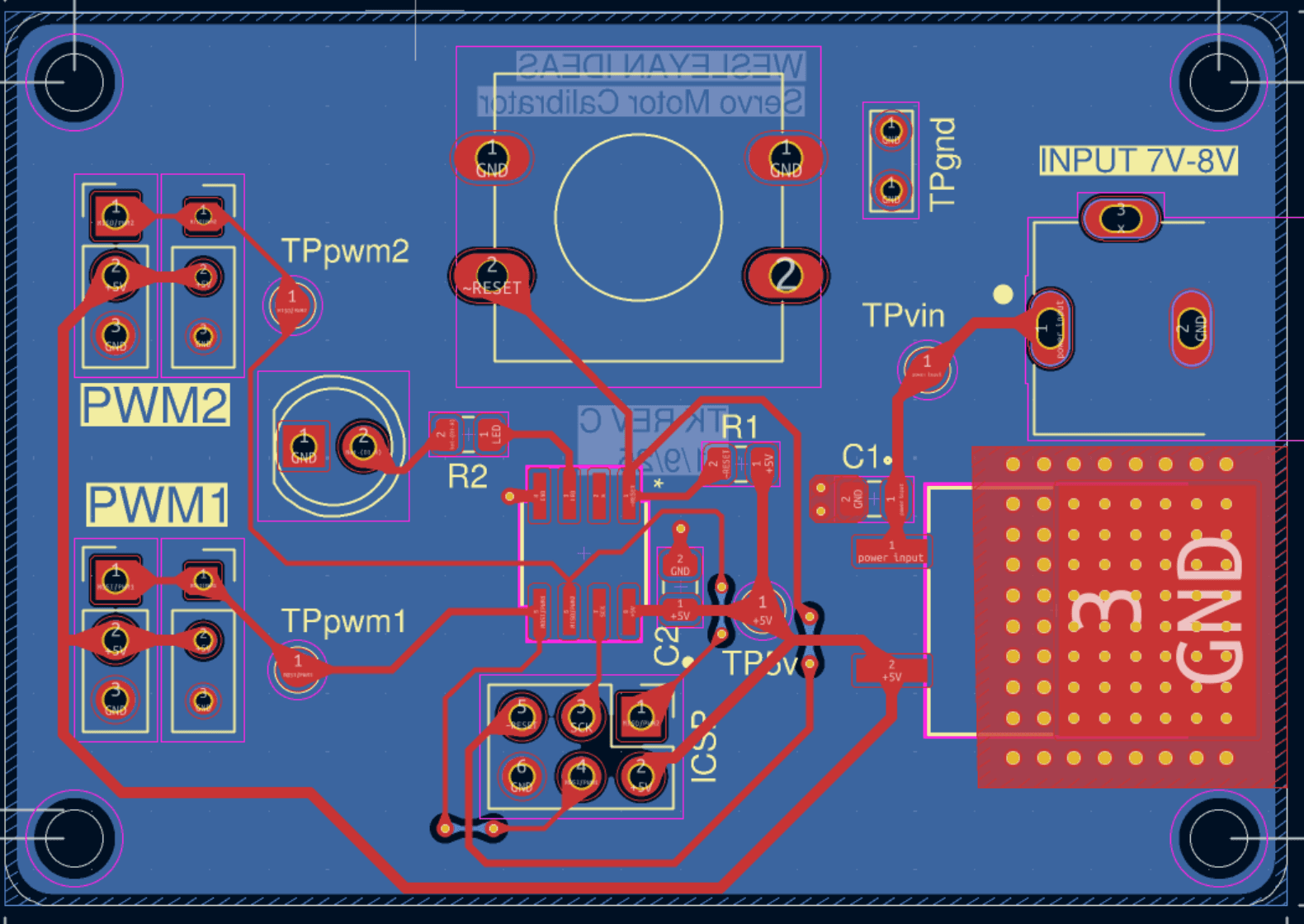
Layout and Routing
Then, I layed out the components before routing and went through many different orientations.
I routed with thermal regulation of the linear regulator in mind. I was also mindful about the noise emitted from the SCK ICSP line.
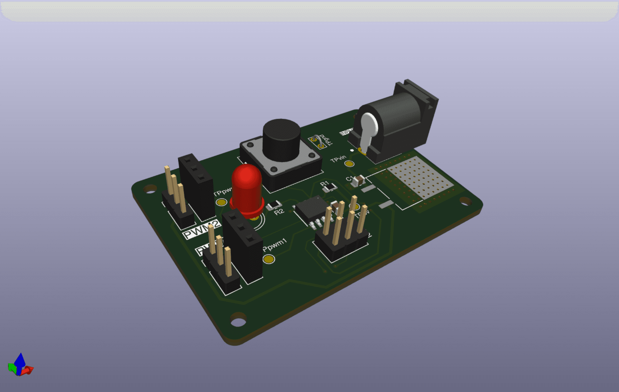
3D View
Finally, I generated the gerber files for manufacturing.
Assembly
I cut a stencil out by exporting the paste layer of the gerber file and using a CO2 laser to cut it out on mylar. Rather than buying a more expensive aluminum stencil.
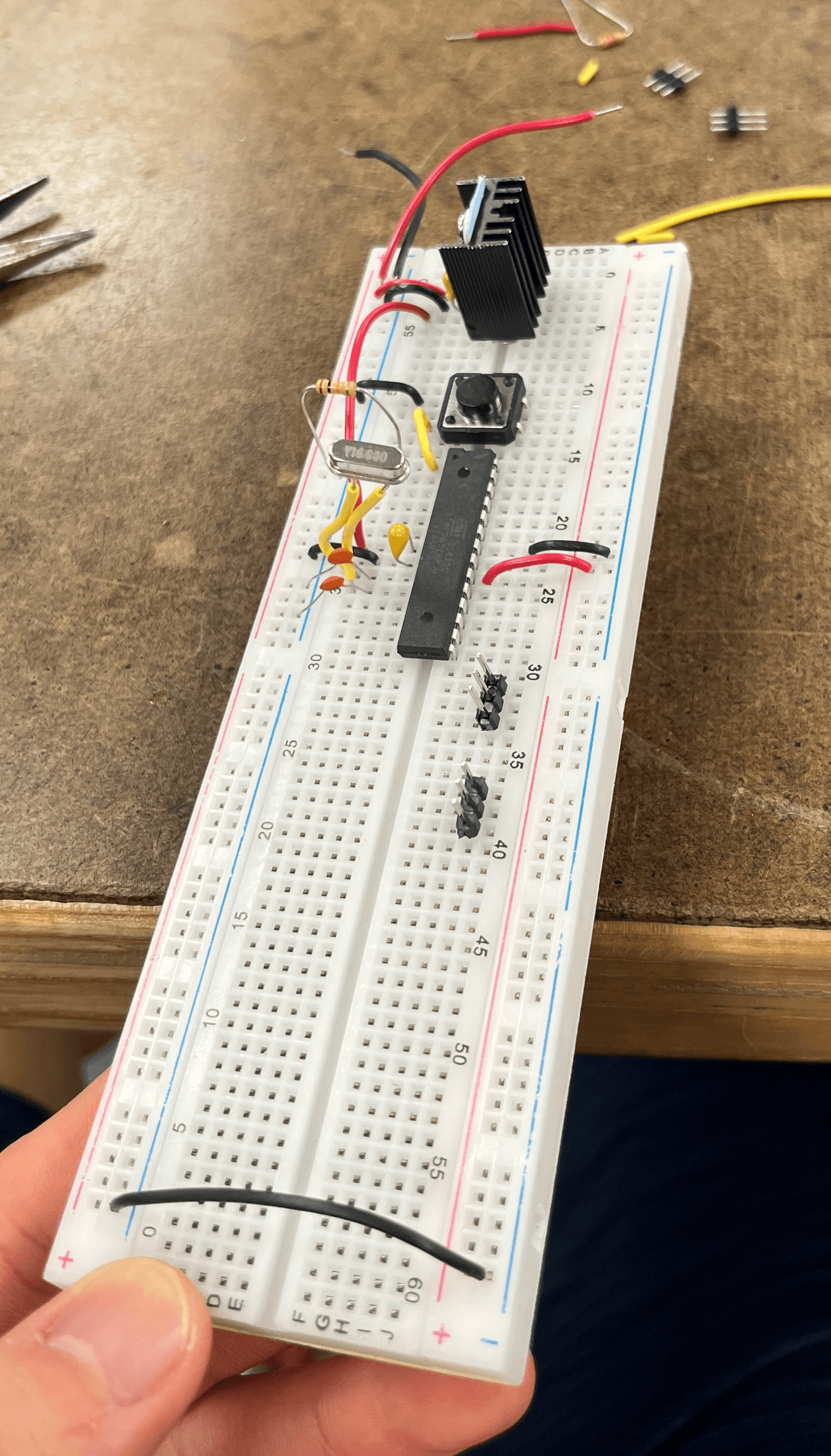
I initally used an ATMEGA328P and a spare 5V regulator to test proof of concept.
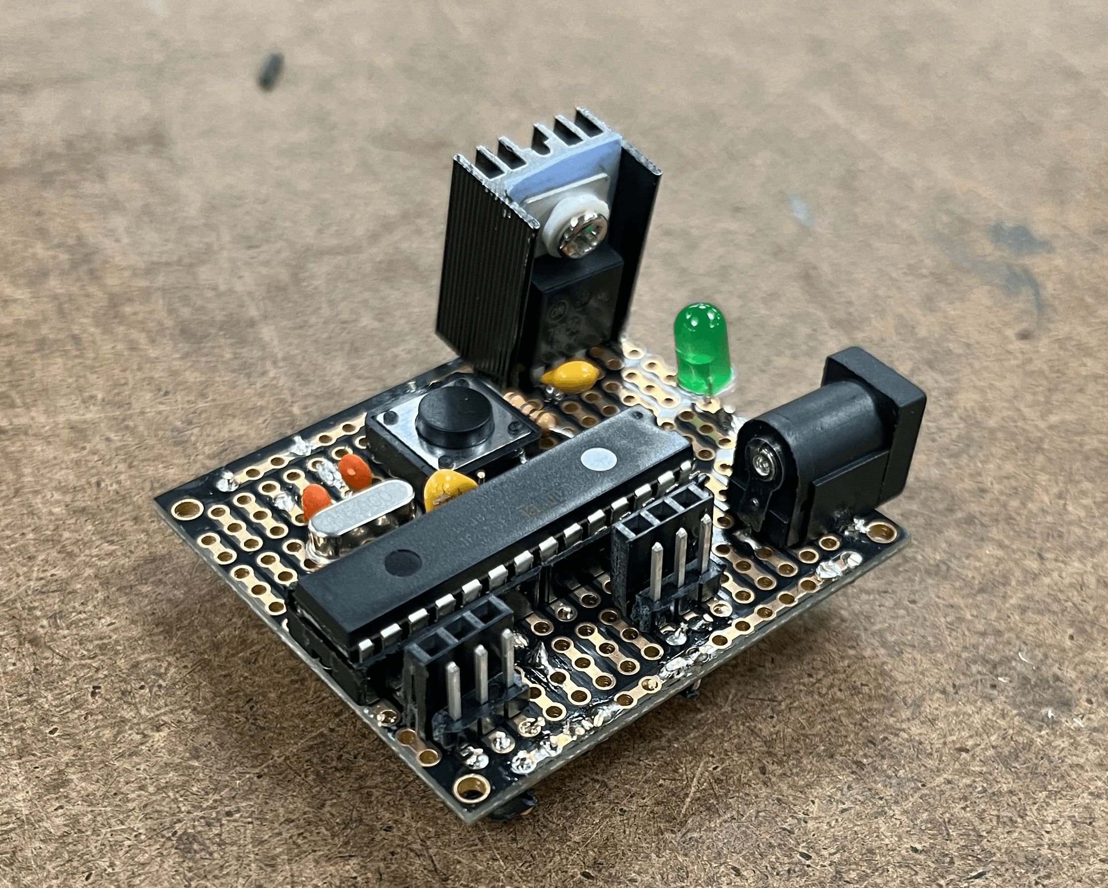
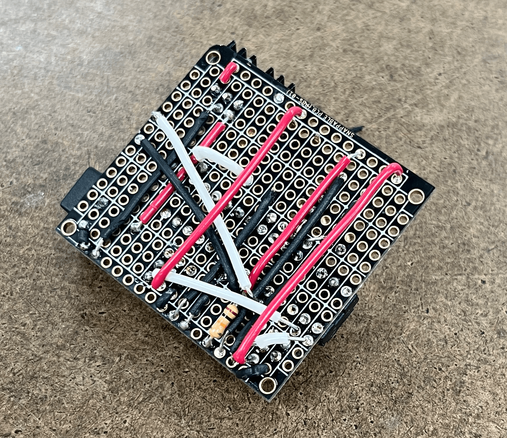
Protoboarding
Then, I filled out a protoboard with the components to build a temporary functional solution.
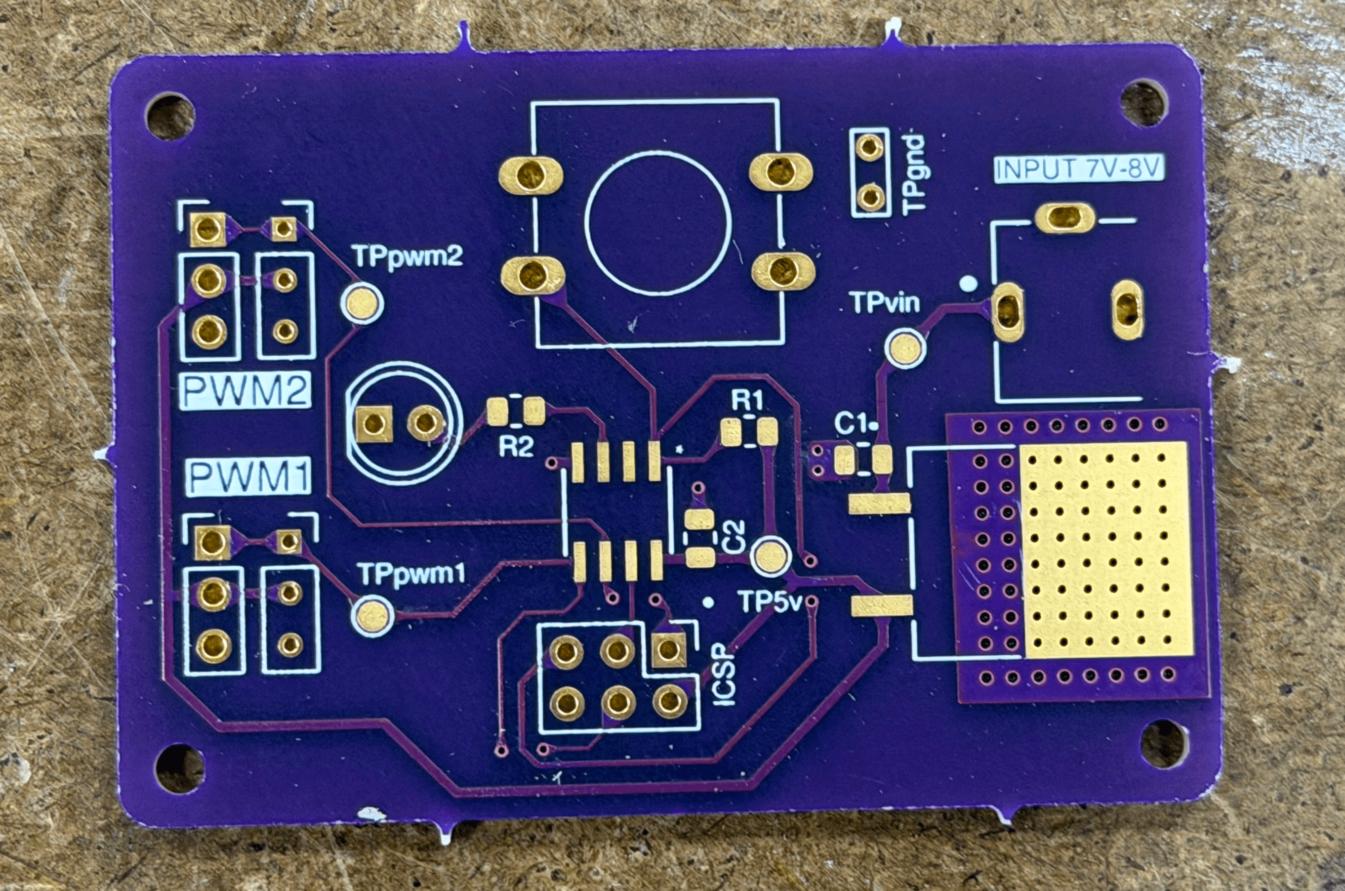
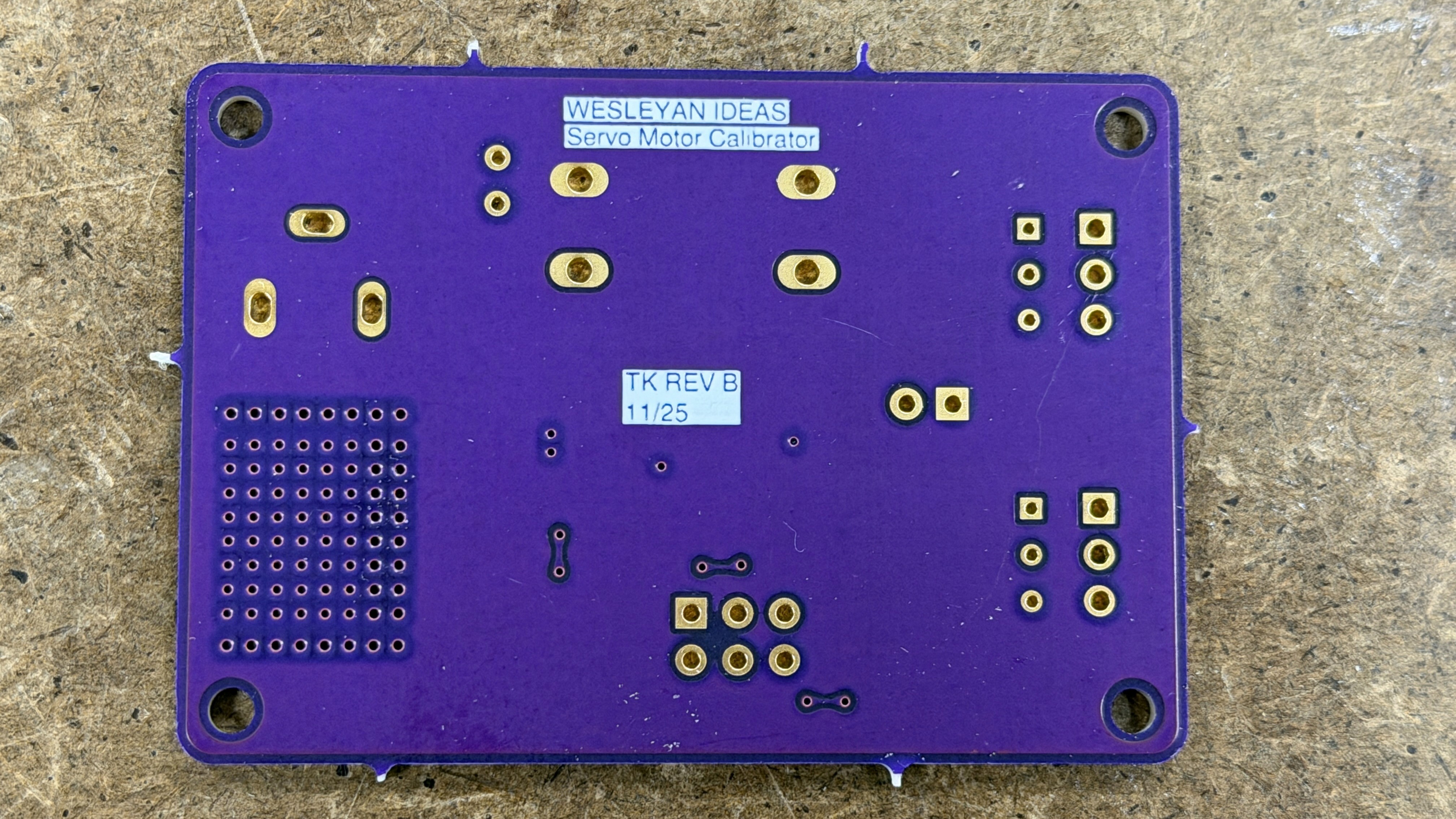
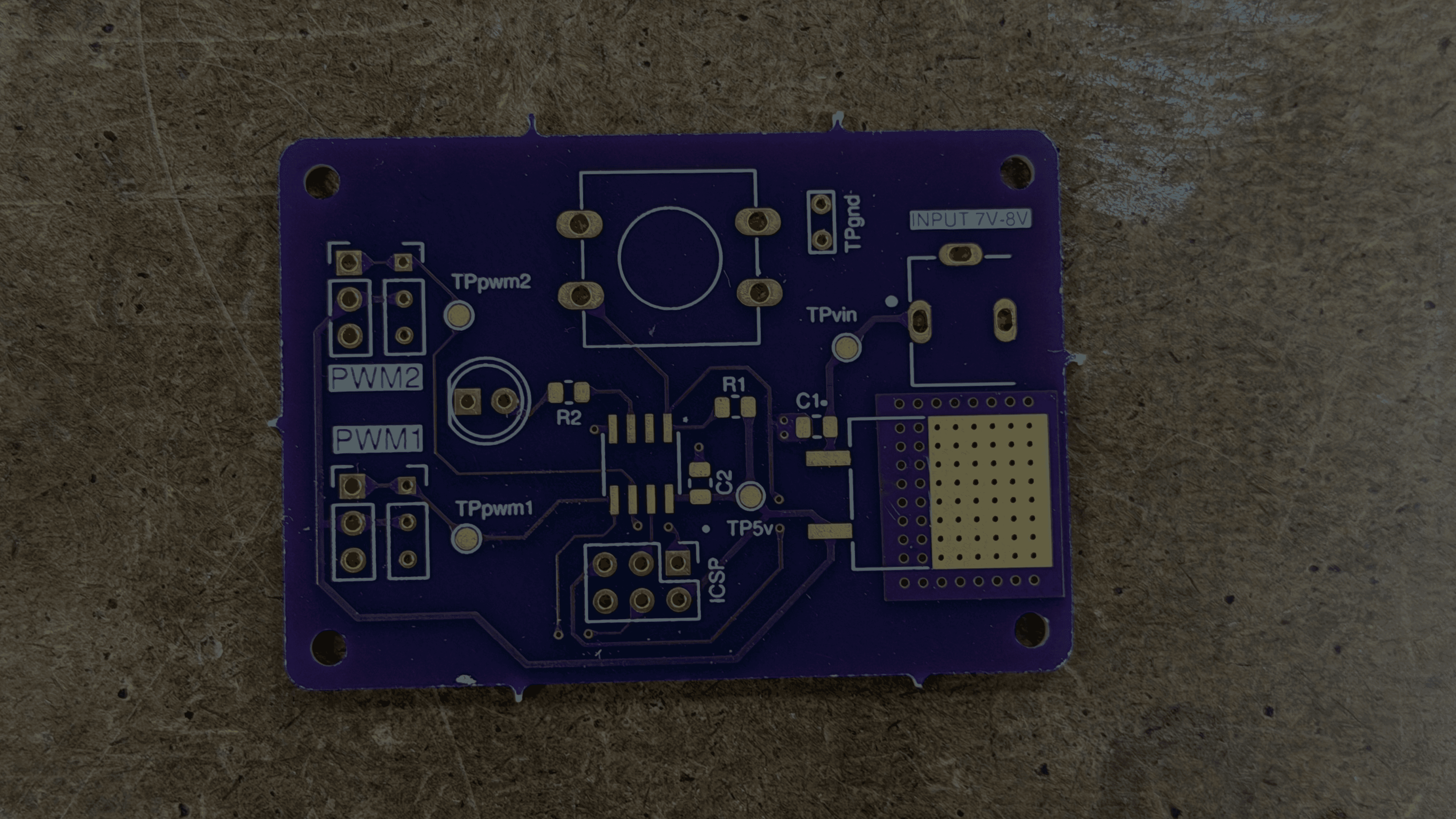
Finished PCB
After a few weeks the final boards arrived.
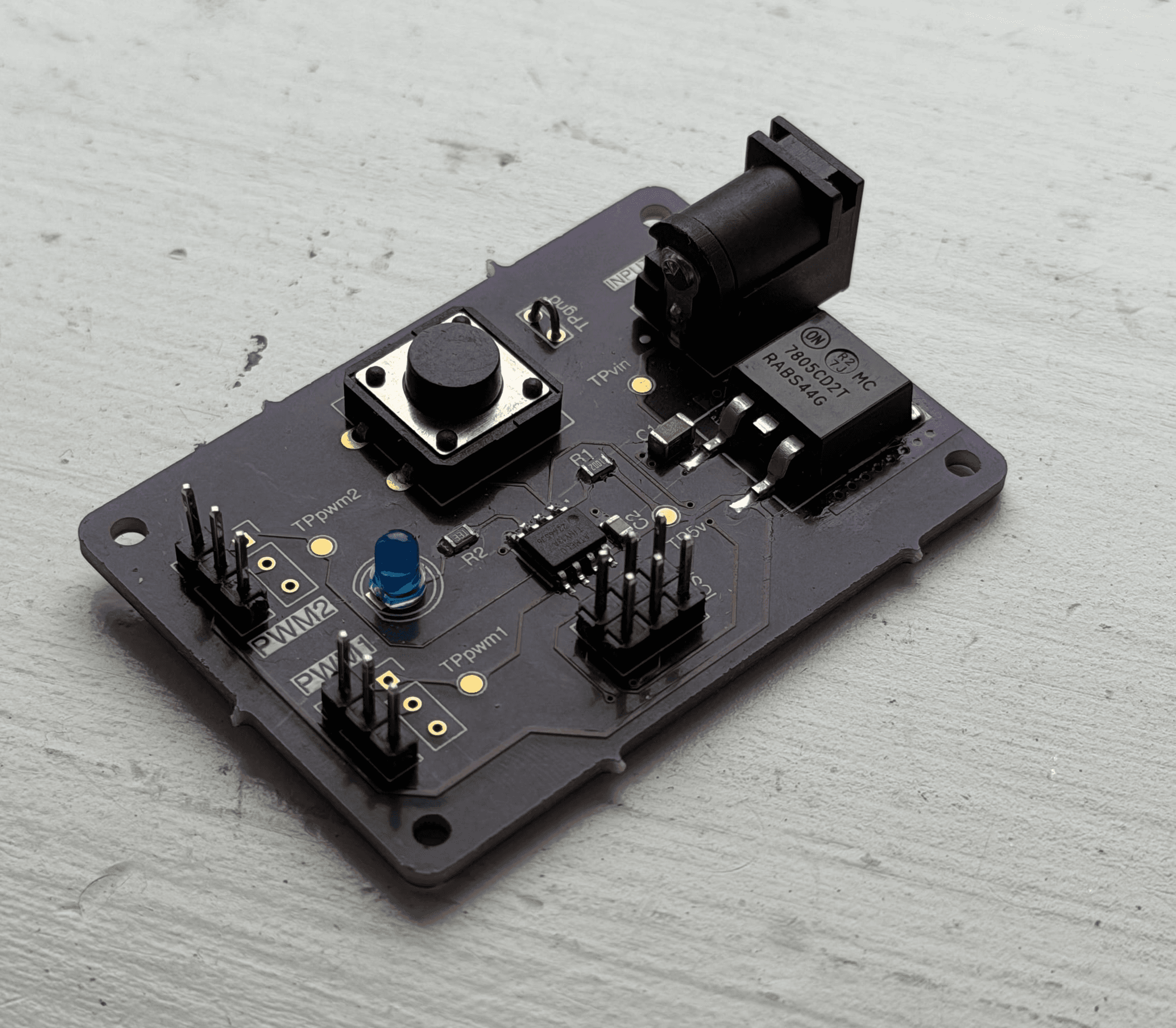
Here is the finished PCB. It was interesting to feel how the heat from the linear regulator spread out across the whole board.
I also calibrated the internal oscillator of the MCU to 9MHz using an oscilloscope and Atmel's calibration scripts. That way all 3 boards sent identical PWM signals.
Top Skills Used
PCB Layout and Routing (w/ KiCAD)
C Programming
Hardware Debugging w/ Oscilloscope


